![]()
|
3DColorMultiMFD Installing |
|
|
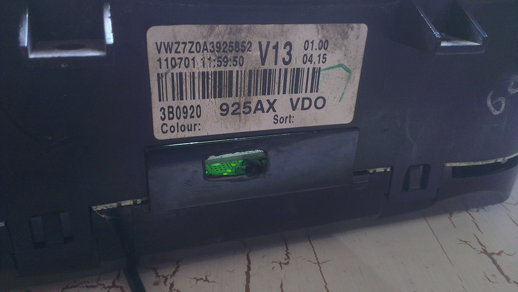
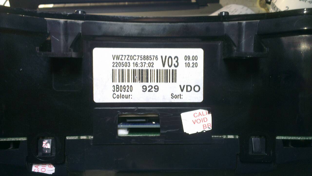
Mounting, module version 7.5 |
|
 |
VW T4 T5 2003-2010 |
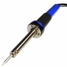
You will need:
| Soldering iron 40 W |
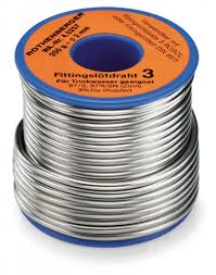
Tin |
Flux |
 |
 |
 |
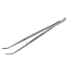
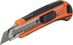
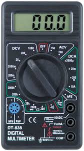
| Tweezers | Knife | Tester |
 |
 |
 |
|
Thermocouples |
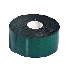
And double-sided scotch tape. | Nippers |
 |
 |
 |
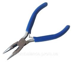
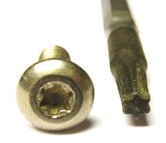
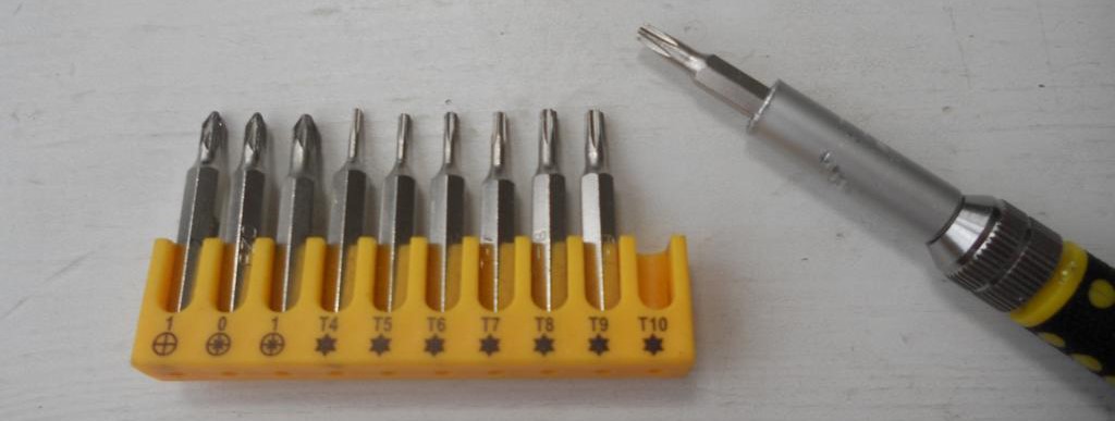
| Pliers | And screwdriver Torx T10 | |
 |
 |
|
|
Safety precautions DO NOT! |
||
|
|
||

When installing a color MFD, there are 3 most important points.
1. You need to configure the power supply to 5.5v.
The module
operates at a voltage of 5.5V. When you connect the power supply to
the module you should make sure that the output of the contacts is
5.5v, otherwise it will damage the processor! Paragraph
18
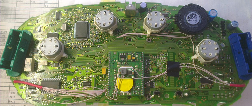
2. It is necessary to cut the power paths going to the pins 23 24
25, then
check that they are not voltage-free, you need to supply power to
the cluster and check with a tester, one probe into the ground of
the second to each pin 23 24 25. Should be 0V . Paragraph
10
3. You need to rinse all the soldering points. Install very
carefully.
After soldering
the wires, it is essential to rinse the soldering points with
special flushing agents or isopropyl alcohol. During washing, do not
allow alcohol to enter the display or under the display and its
board!
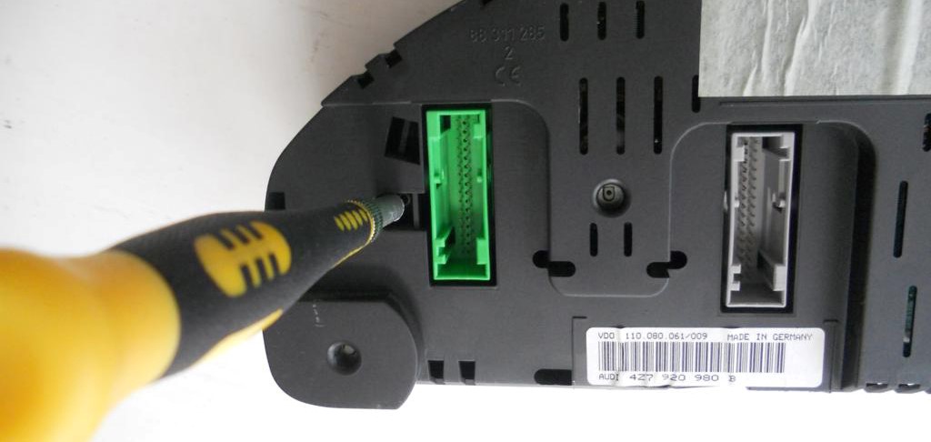
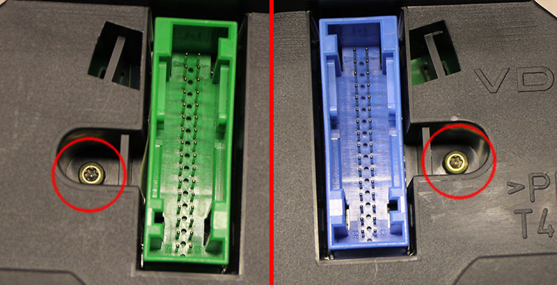
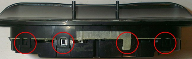
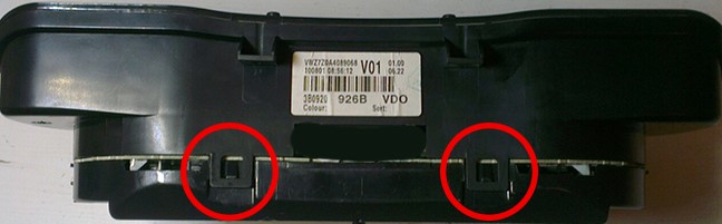
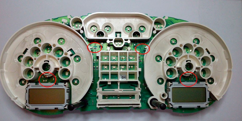
1. We disassemble the device.
With a screwdriver torx T10, unscrew the two screws edges on the rear of the instrument panel.
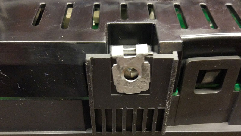
Bend all the latches neatly remove the front of the case with glass
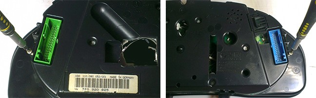
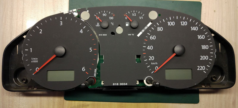
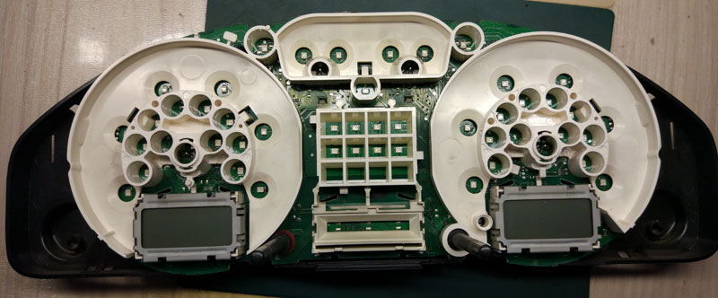
View from above
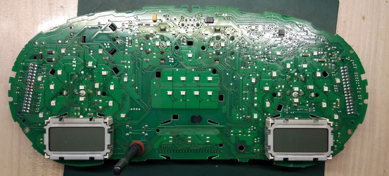
Bottom view
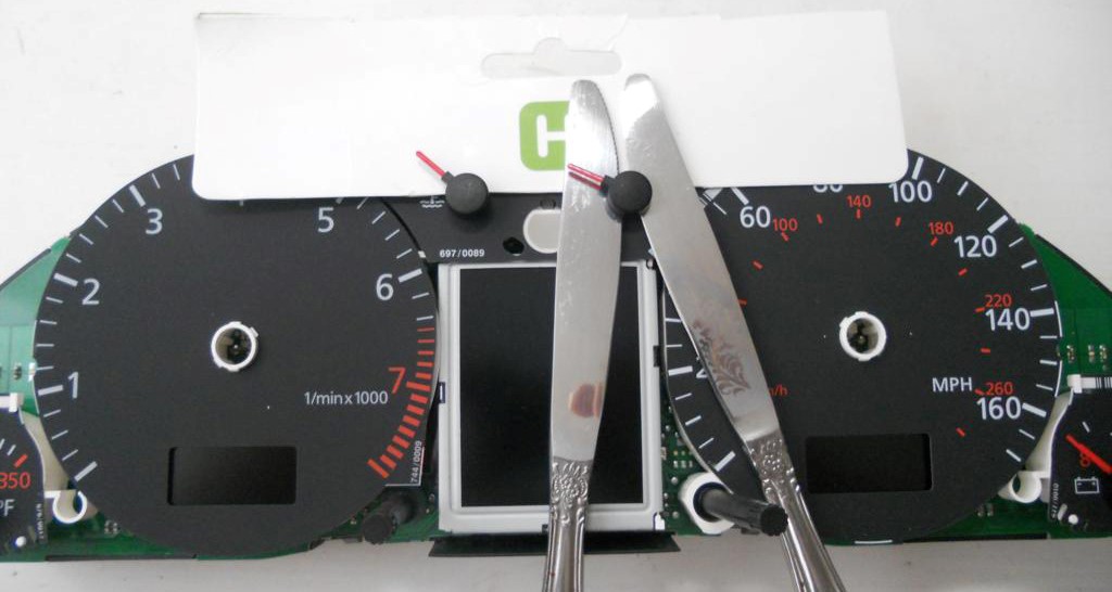
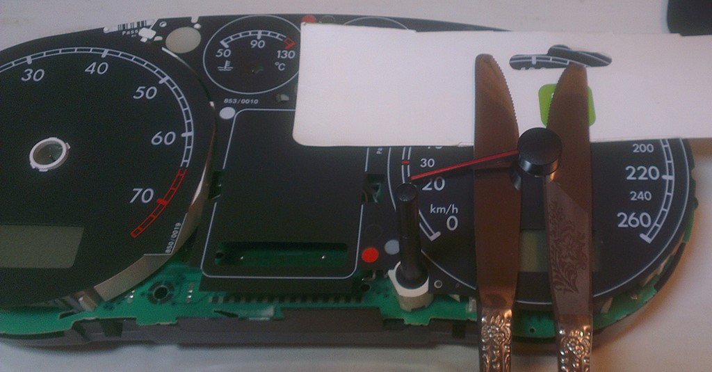
1. Remove the arrows (scroll counter-clockwise and simultaneously pull ourselves).
Either Using knives for oil or spatula, shoot the arrows from their shafts. It is necessary to put
A cardboard or napkins between the nomes and the base of the device to avoid damaging it. Necessary
Pull the arrows up to yourself.
3. Then remove the substrate.
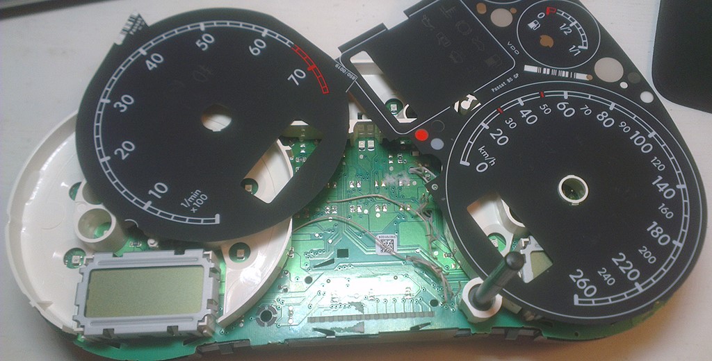
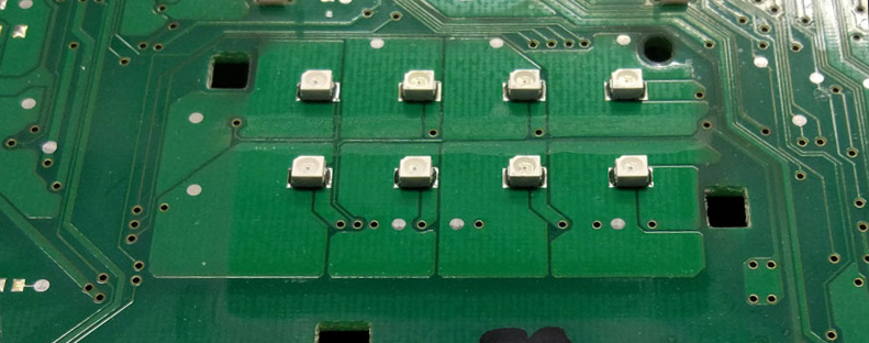
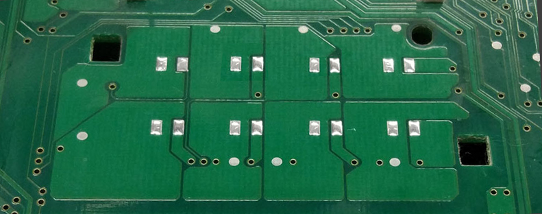
4. Cut the jumpers, we work carefully, so as not to damage the board.
It should look like this:
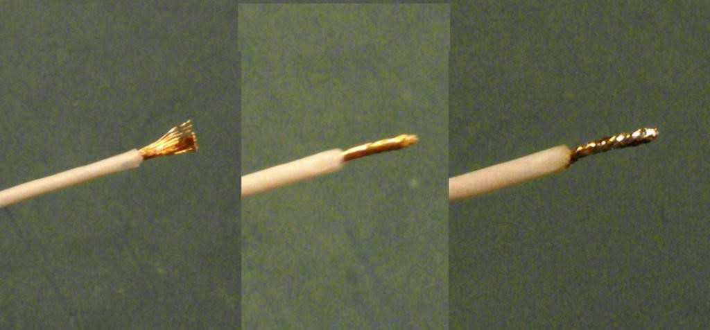
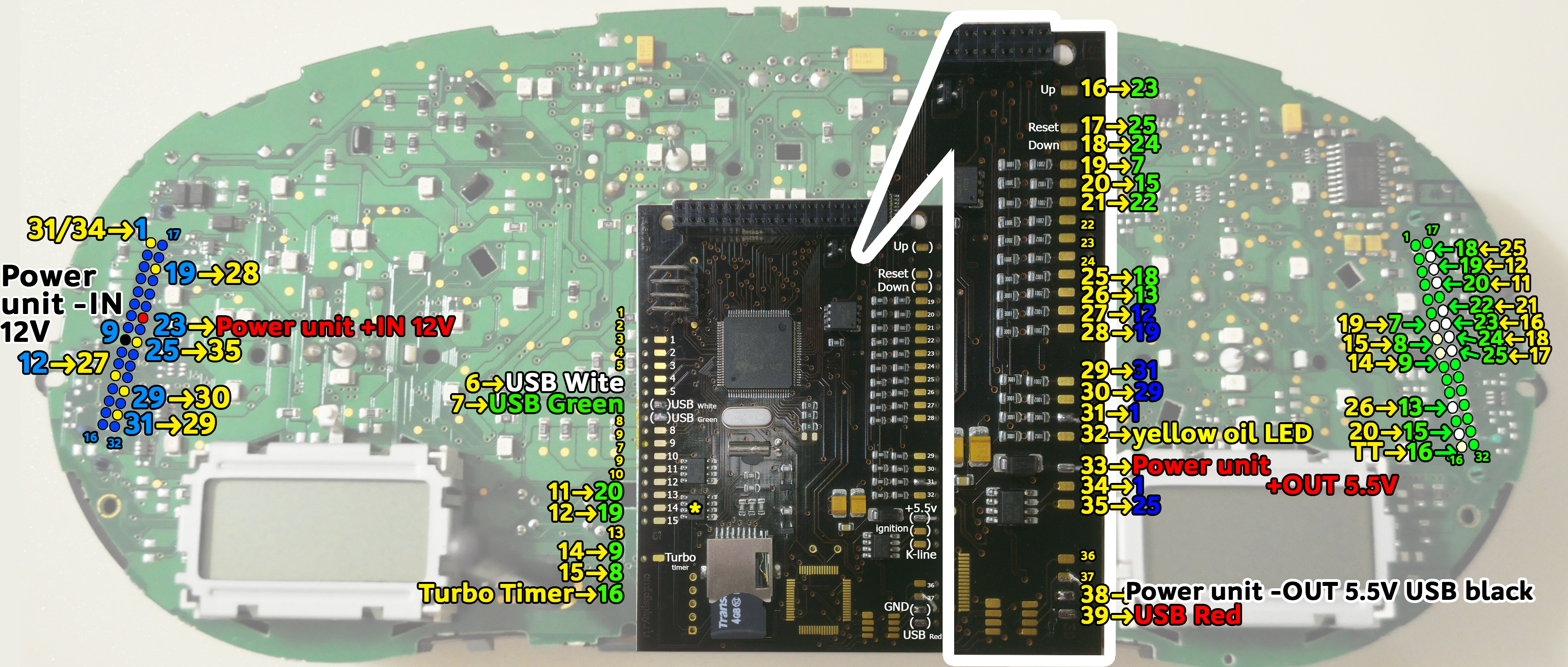
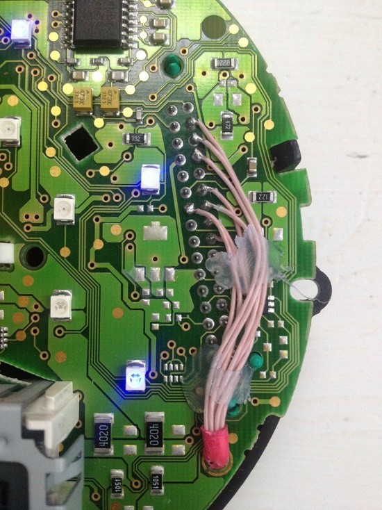
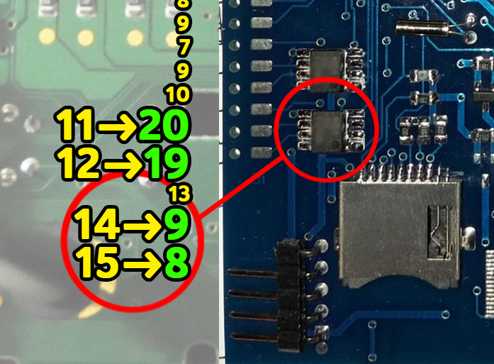
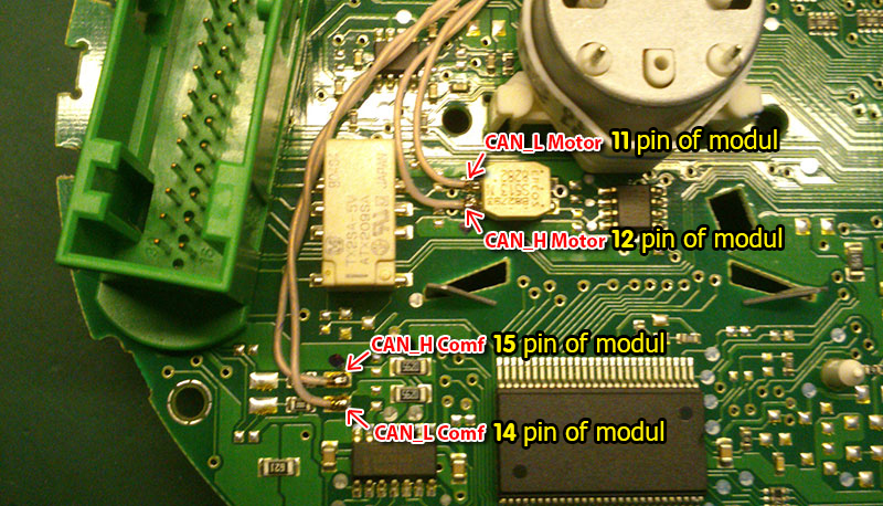
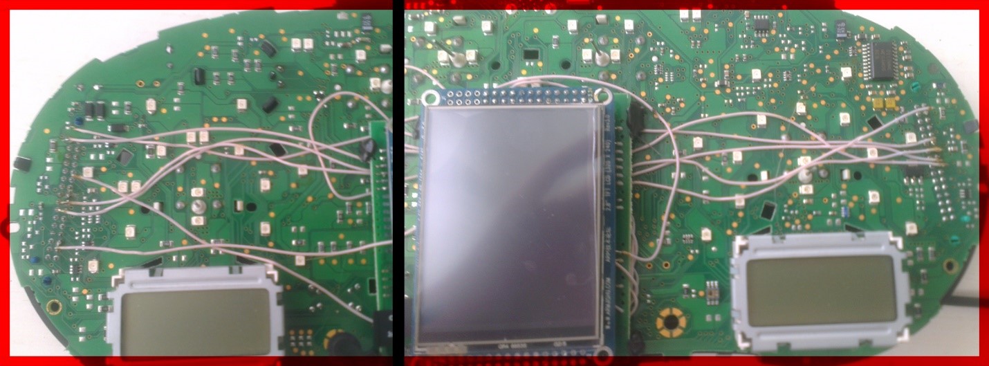
11. We start to build wires according to the table. Wires are cleaned of Isolation and twisting, ludim and cut off excess.
12. Through the holes in the board of the device, we extend the wires to the blue and green connectors.
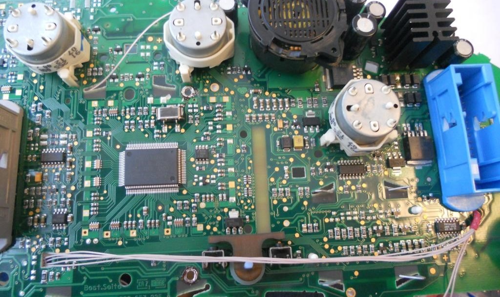
13. Using the tester, we find the wires we need and solder them to the feet connector according to the table.
1-st Option
Also, for
ease of installation, it is possible to solder the wires either
according to the diagram above or from the back of the instrument
panel chamber.
2-nd Option
Lay the wires in such a way that they do not interfere with the installation of white light diffuser.
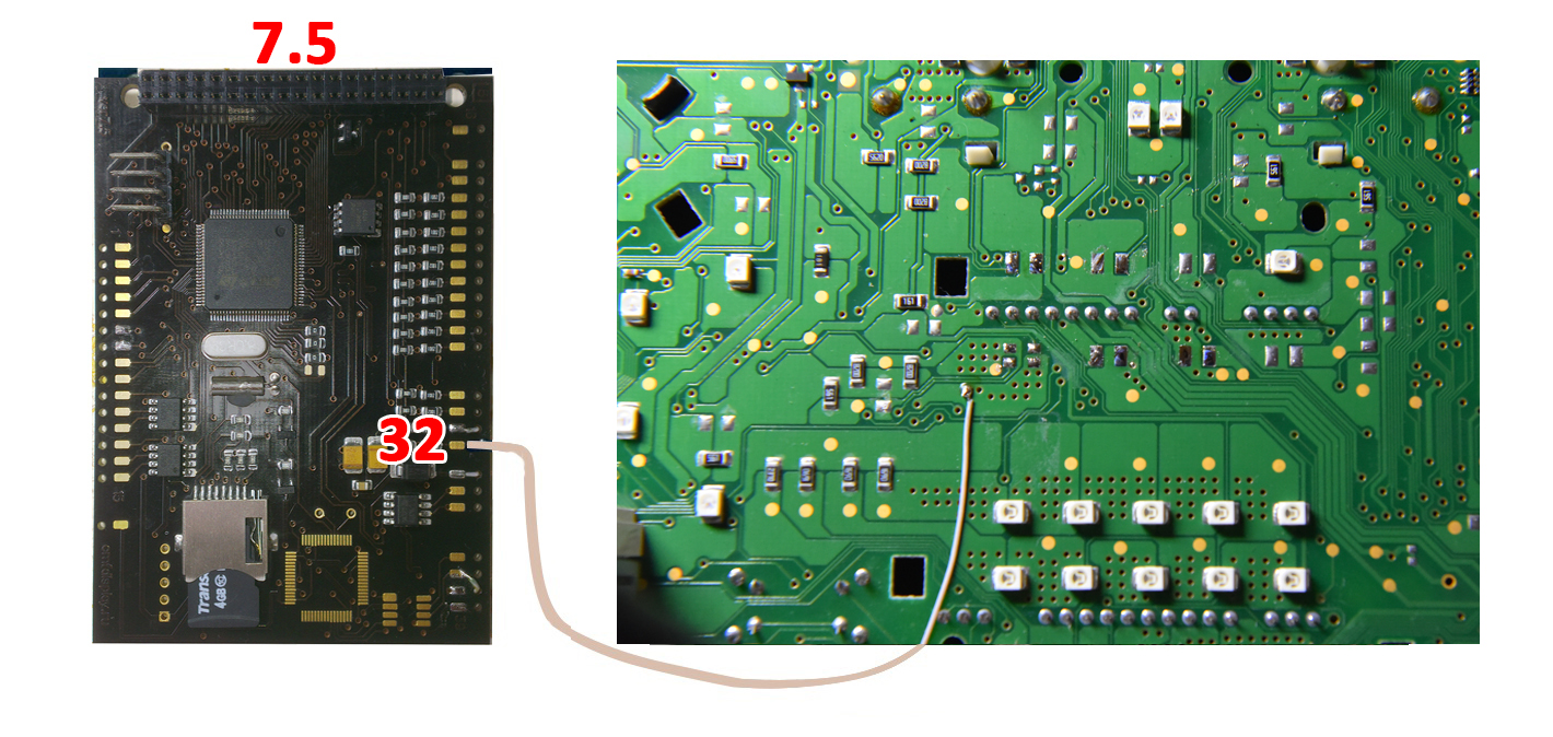
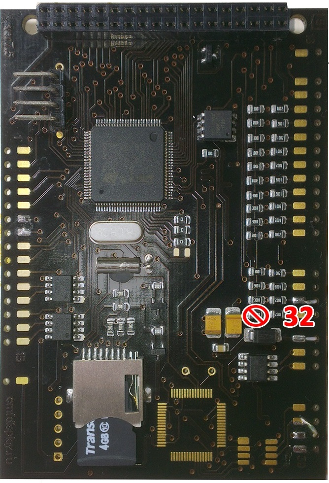
14. On
the cluster without FIS
and with halfFIS it is necessary to
solder the wire from the 32 pin of module
slots to the oil LED on the board.
And on the instrument panel with a FullFIS, this wire
does not need to be soldered!
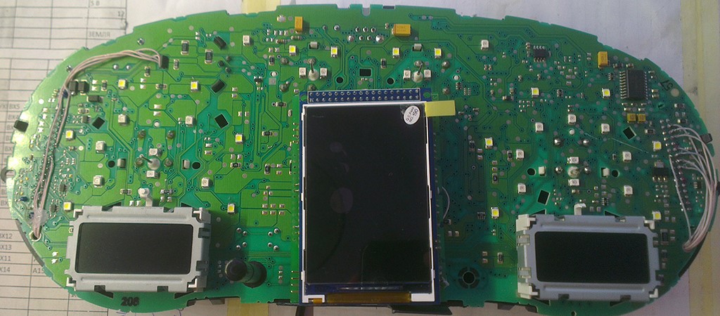
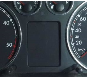
The dashboard with noFIS looks like this:
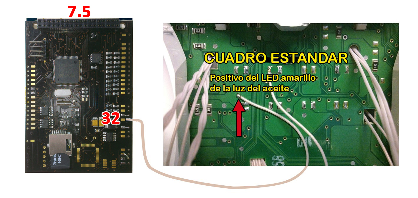
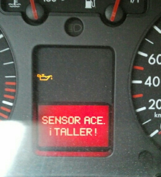
The dashboard with halfFIS looks like this:
Resistors instead of light-emitting diodes, as on a photo, it is not necessary to solder, we leave an empty place.
Important!
If you have half FIS or no display at all
It is necessary to sting this resistor from the module board
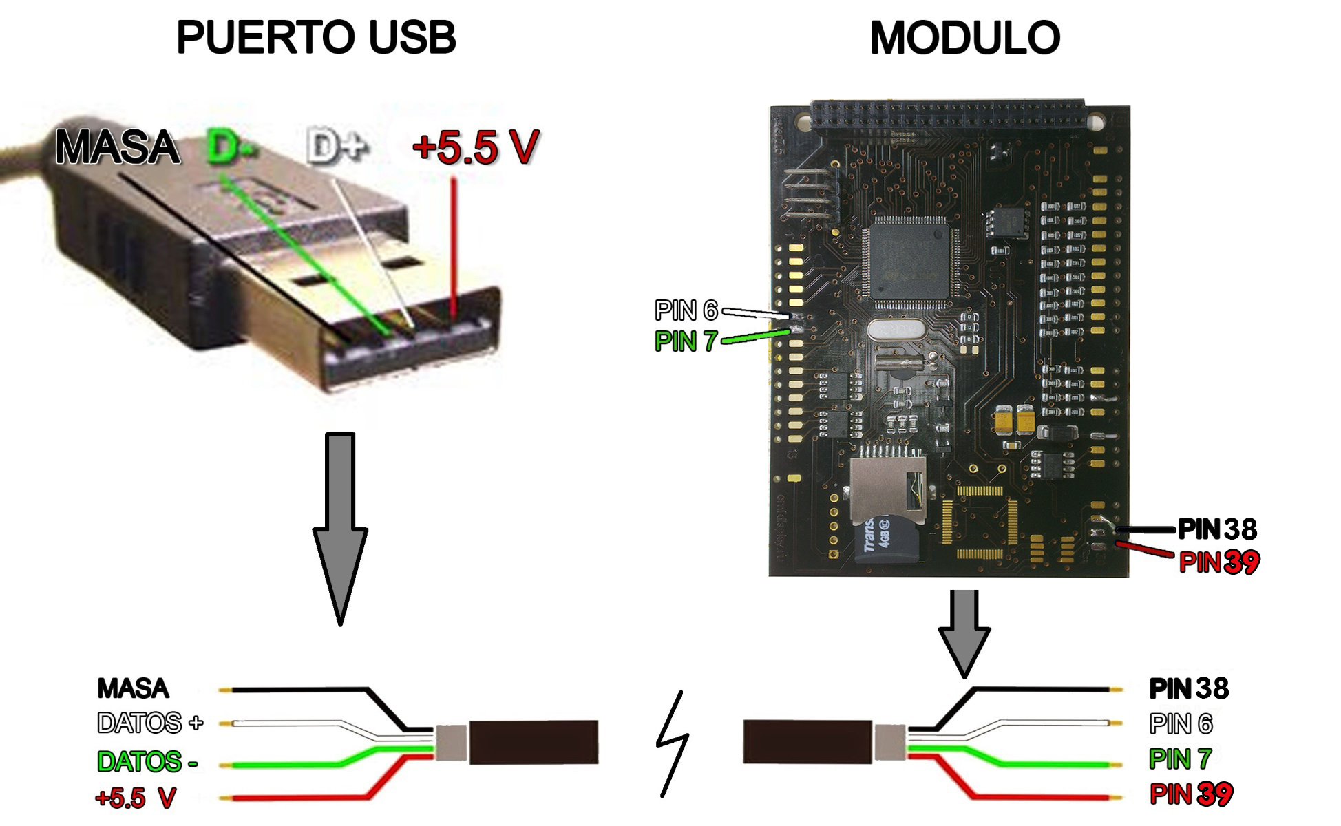
15.
Connect the USB cable as follows:
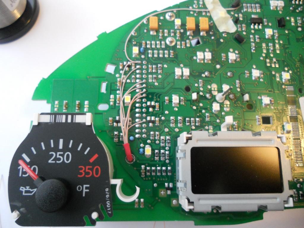
In order for the module to show the temperature of the environment.
You need to add the missing items to the dash board
The dash board does not have a resistor and capacitor.
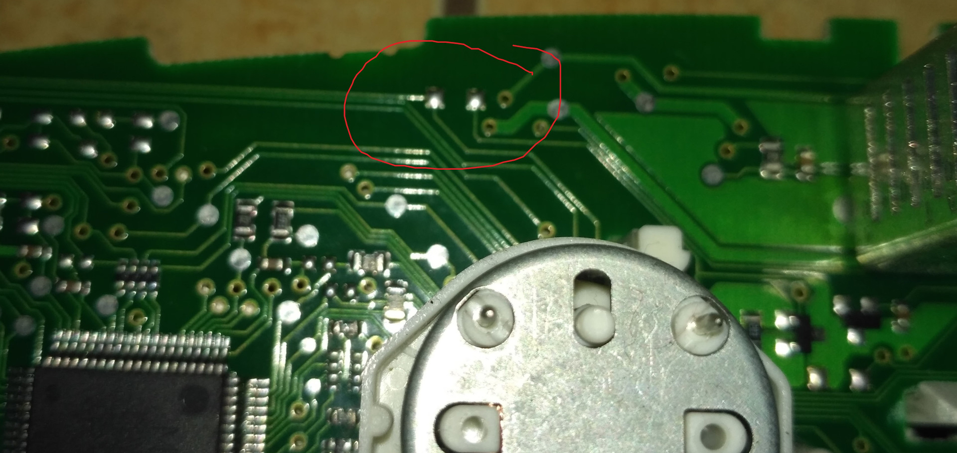
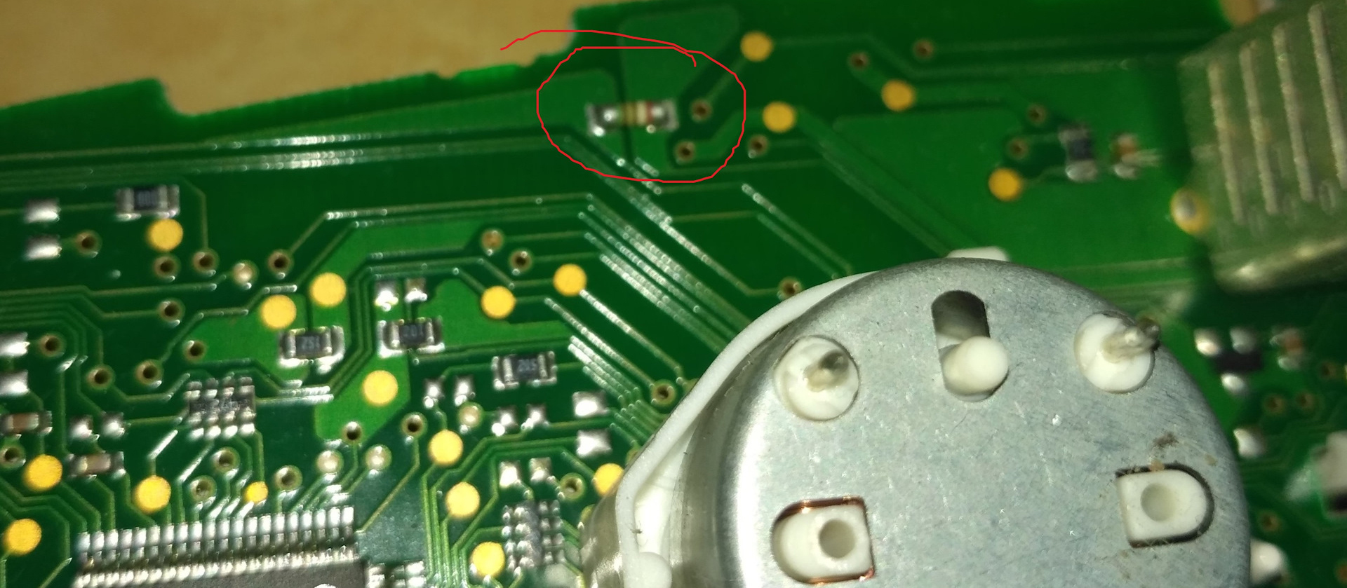
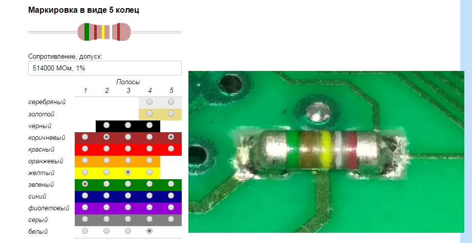
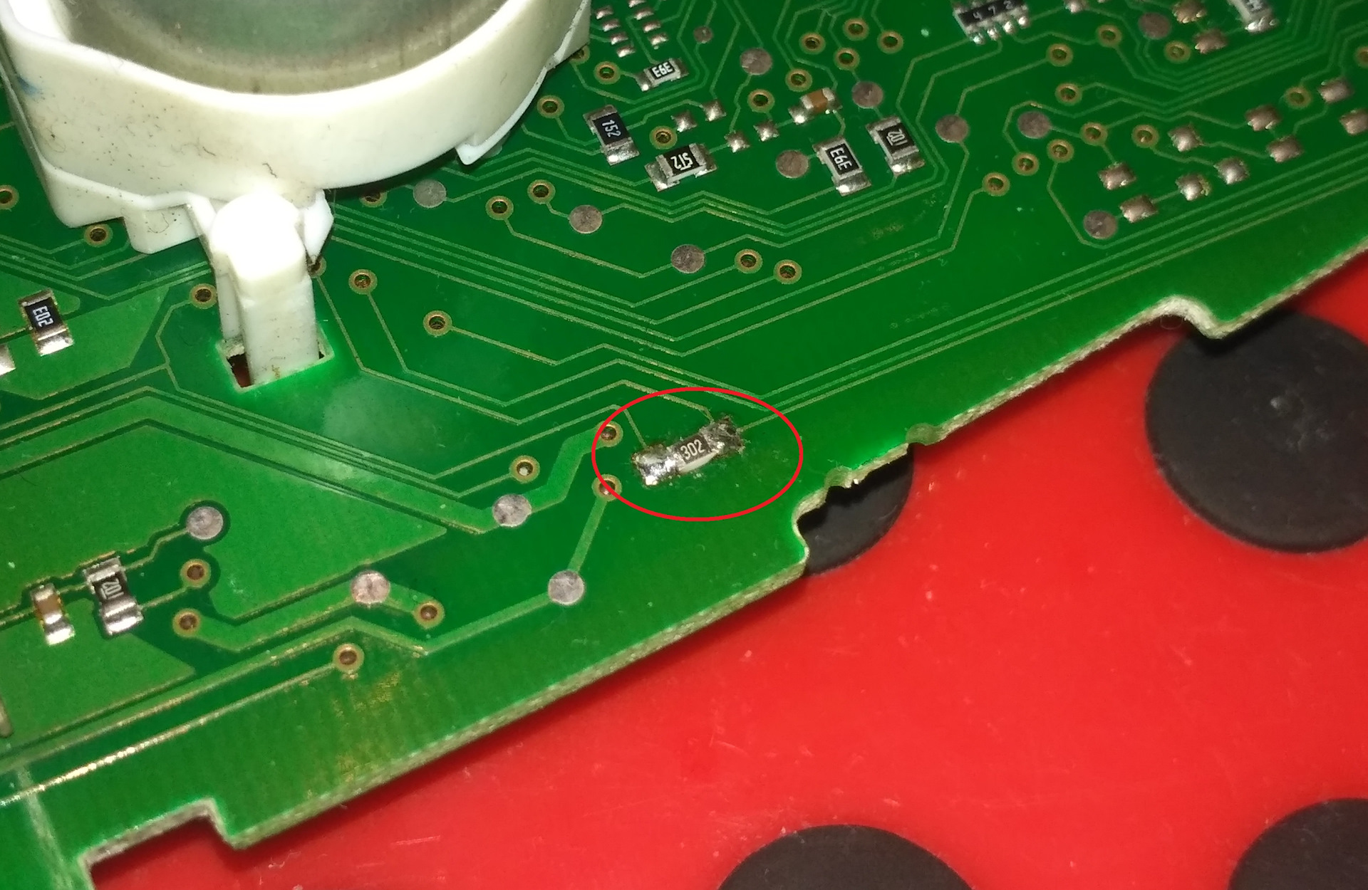
Resistor at 3 kOhm on the back of the board above the motor of the fuel arrow
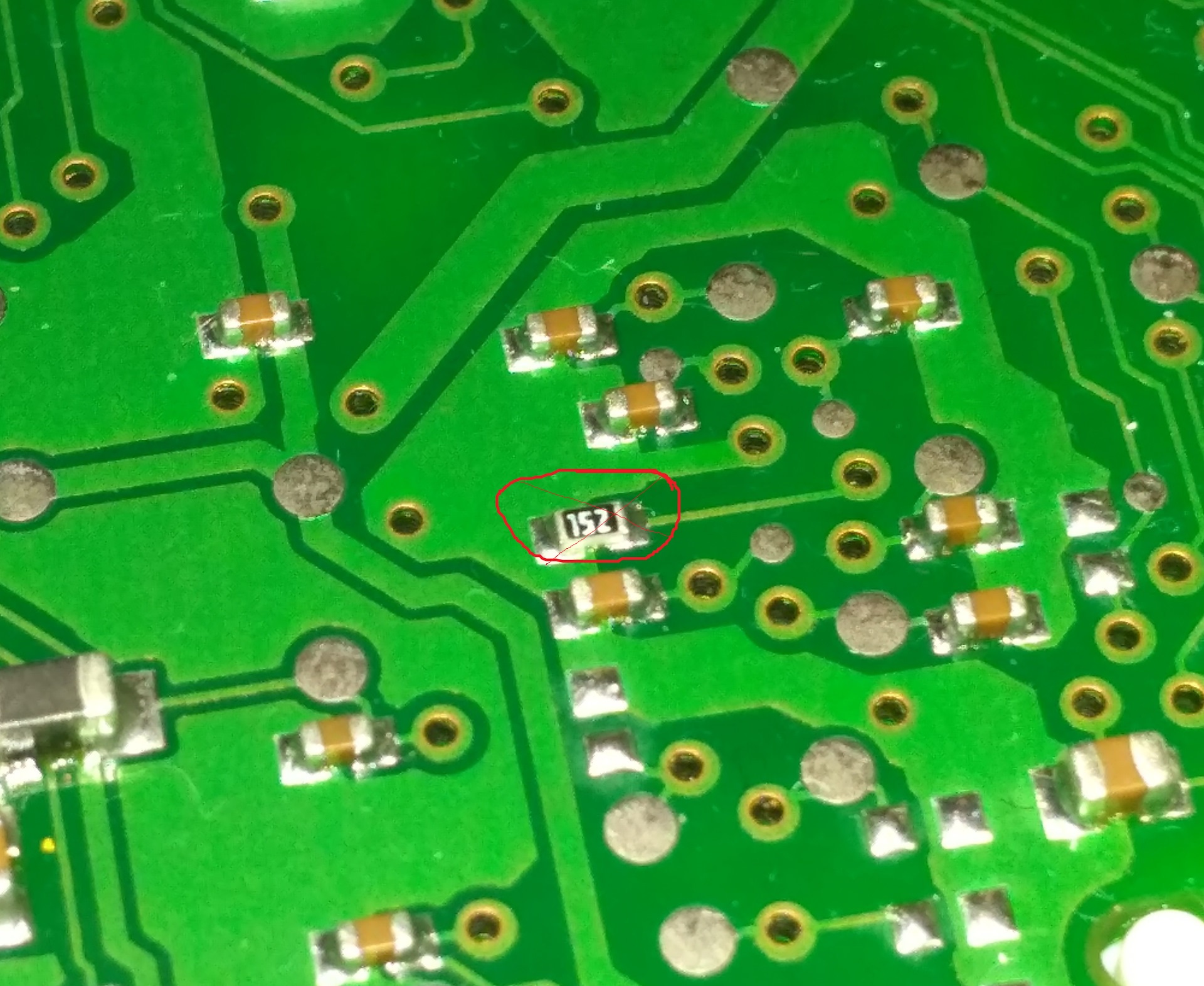
You need to remove a 1.5kΩ resistor to the capacitor - on the input line to the Large IC with a bunch of legs (on the front side of the board under the right side of the tachometer scale)
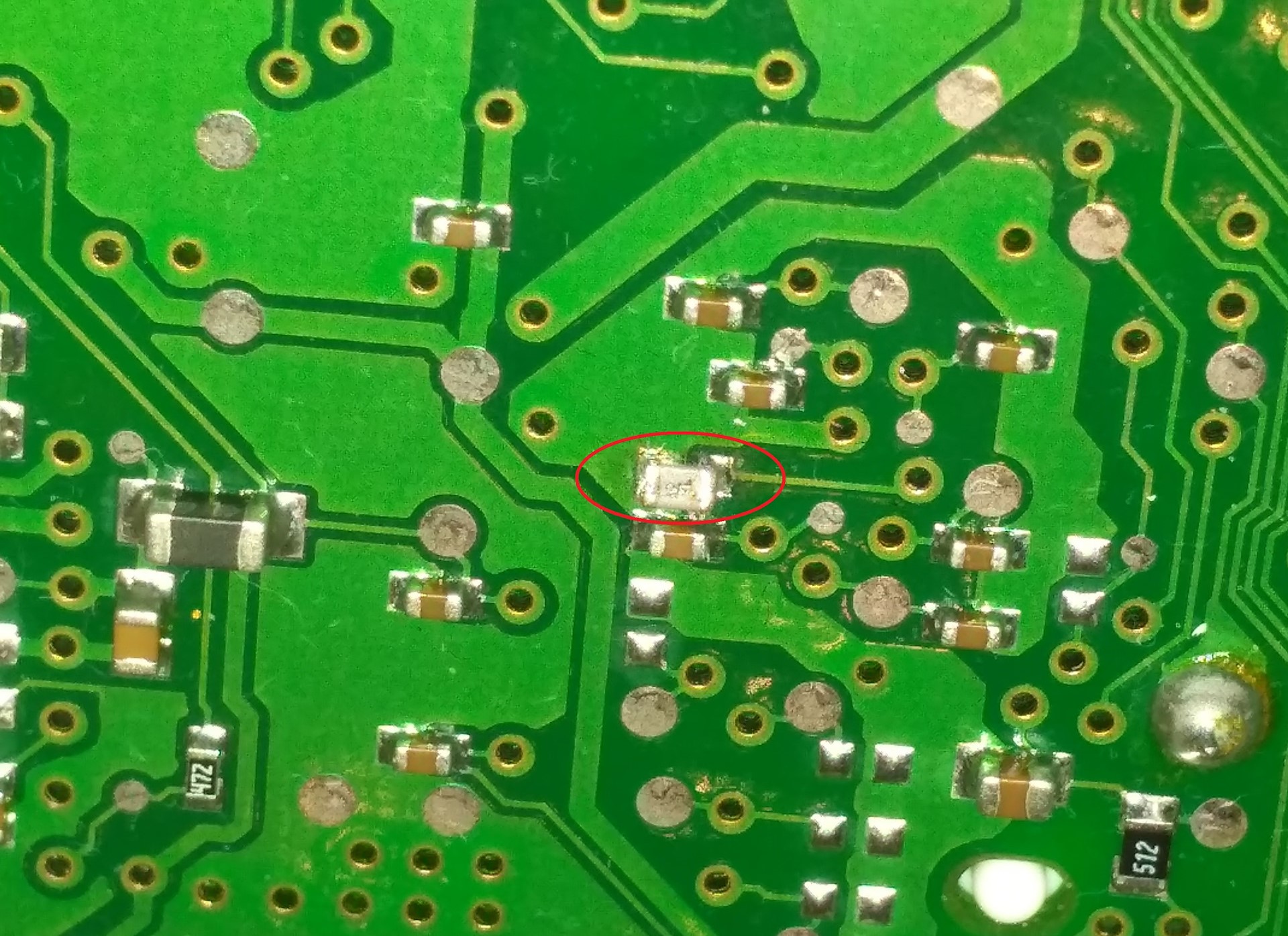
The capacitor rating should be 10 nF
Those. in order for the assembly to show the temperature overboard on the
instrument with 3DColorMFD installed in the instrument without MFA (half or
full screen), it is necessary:
1. Solder a 3kΩ resistor
2. Replace the 1.5kΩ resistor by the capacitor on the input line to the
microcircuit
3. Fix dumping device - turn on the temperature input in the eeprom. The
dashboards are different for T4, so if it's the same type as VWK501, it's
enough to change:
address 0x178 - value 00 to 01
address 0x1E5 - 2B on 2D
Many thanks to
VampireLo for his excellent work on finding and fixing this problem.https://www.drive2.ru/l/470939797825781931/
16. If you are the lucky owner of Passat B5 released for the North American or USA market, you have to add a few SMD resistors to the board of the device.

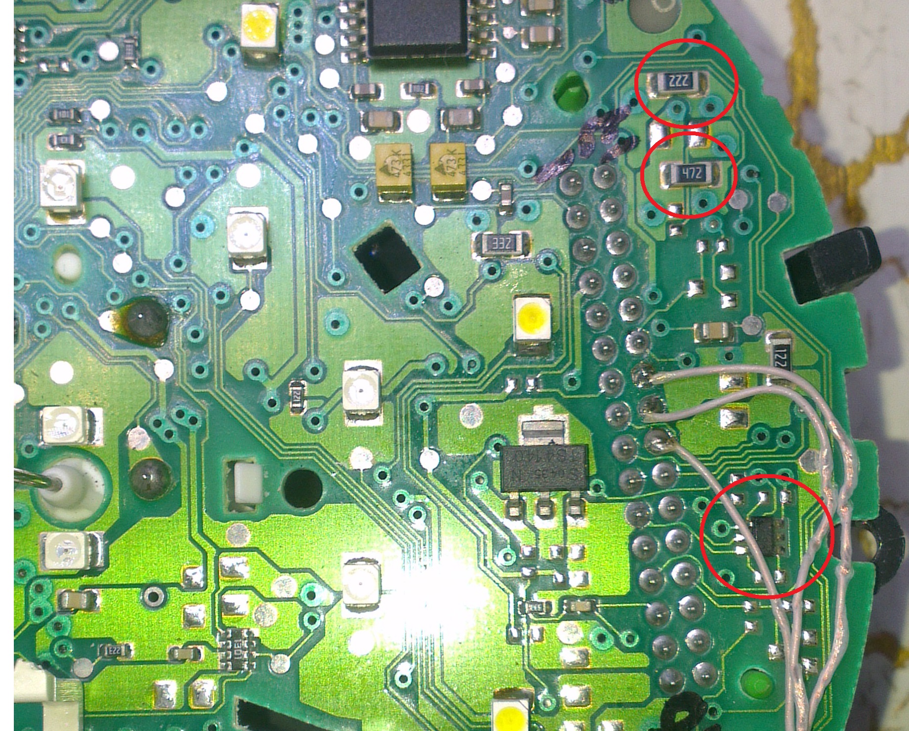
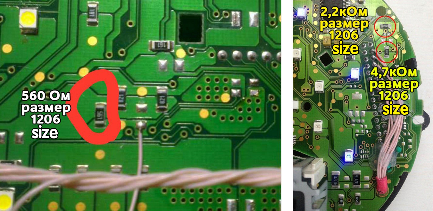

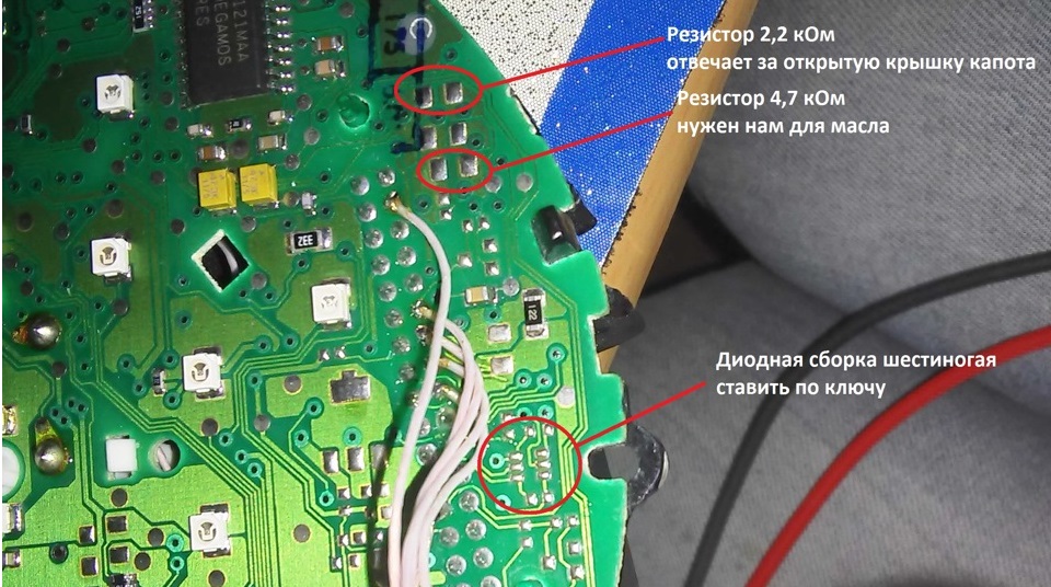
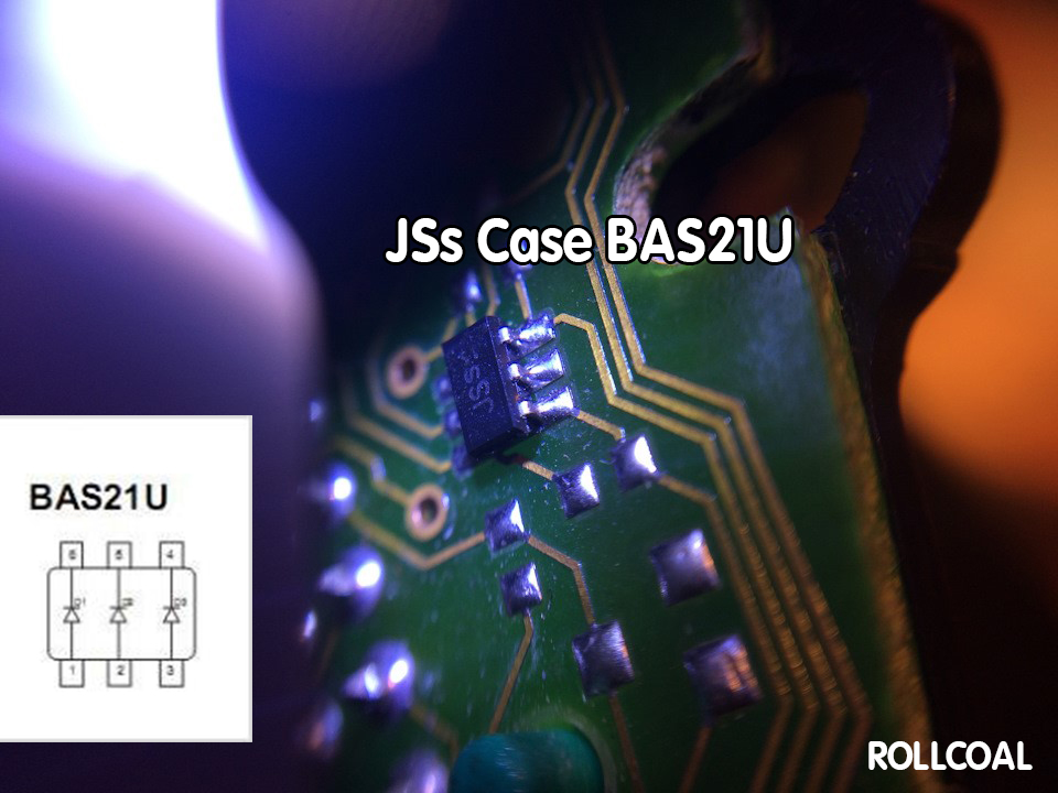
Since Americans do not bother at all about the engine oil. In the cluster for the American market there are no resistors responsible for the level alarm and Oil temperature, and the opening of the hood.
17. Wires should be pulled from the back side Or as shown above, so they do not interfere with the assembly of the device.
So it's not right!
Attention!
18. Before installing the power supply, you need to solder the wires to it contacts + IN - IN and + OUT - OUT , then apply a current of 12V to + IN - IN , and connect the + OUT - OUT wires to the tester.
Now we need to adjust the output current. Using a small flat screwdriver slowly rotate the special metal knob (figure 1 in the picture.) Clockwise
Arrow, until, at us on the tester will not appear 5,5v in an output voltage.
Next we place the power supply unit on the back side, we bring to its contacts the wires from the blue connector.
9-pin of the blue connector is connected to the e - IN on the power supply board.
23 the leg of the blue connector is connected to + IN On the power supply board,
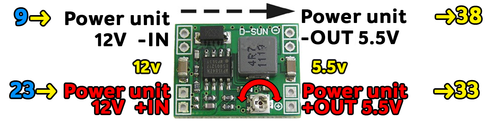
Contact + OUT Connects to the module's 36 pin, - OUT Connects to 43 module pin
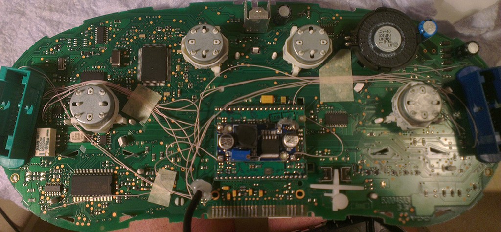
Choose the place of installation of the power supply so that during assembly it does not interfere. Here are the possible
Options:
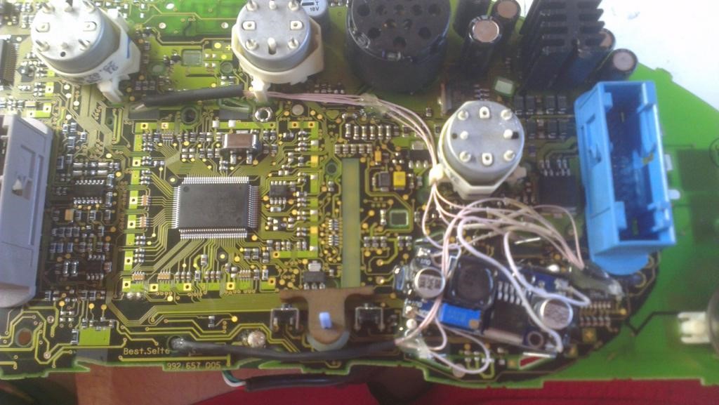
Attention!
After wiring, lay it so that they do not interfere with further assembly. We call all contacts and check on the table to avoid confusion anywhere.
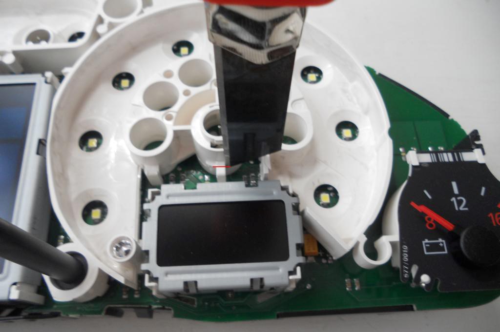
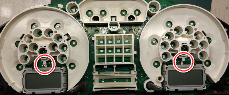
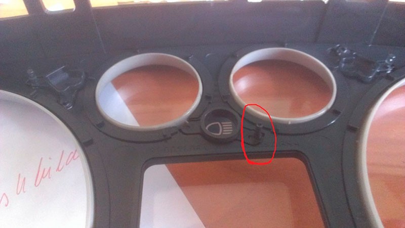
20. Cut off the main beam guide part.
On the red line.
Leave the semicircle.

21. Bite off the protruding part!
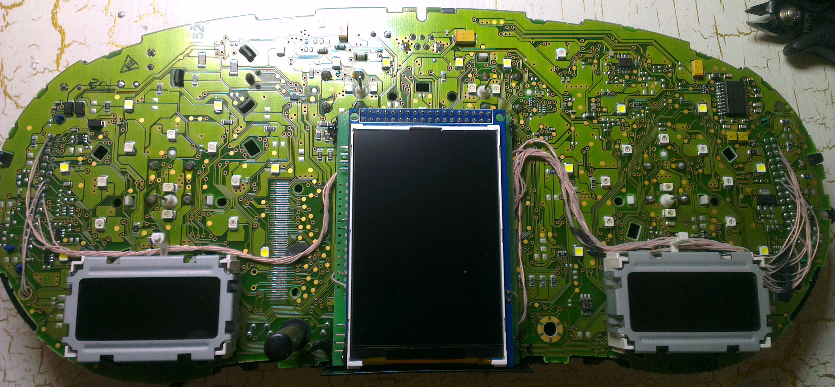
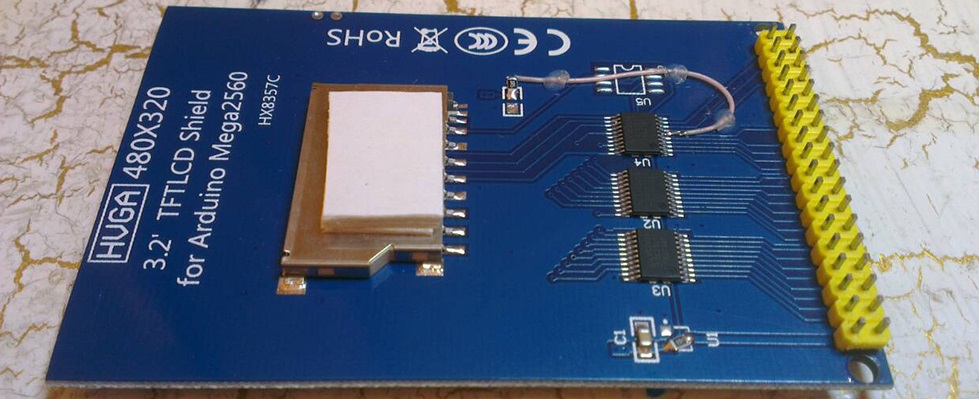
22. Before
installing the display, you need to glue two-way cattle into three
layers on the back of the display to lock the display.
Attention, you do not need to attach modules to the board!
It is enough simply to remove an additional support from a
double-sided adhesive tape without removing the protective layer
from the side of the module board.
23. We take double-sided adhesive tape on a foamy basis, cut the squares 1cm X 1cm.
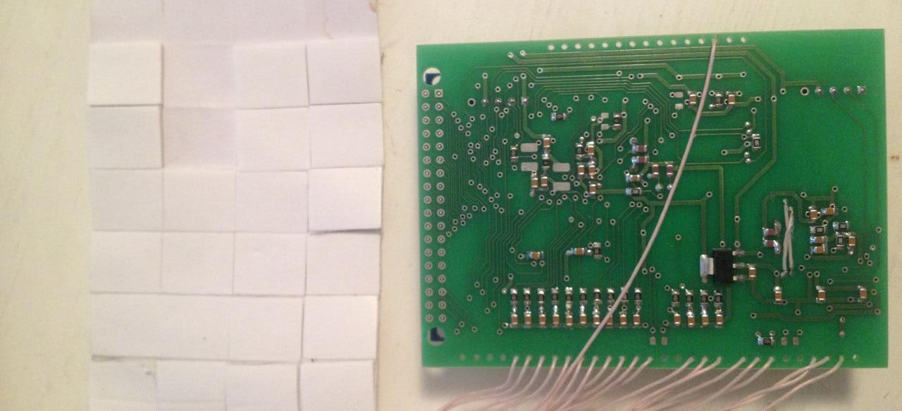
24. We collect these squares in 3 floors.
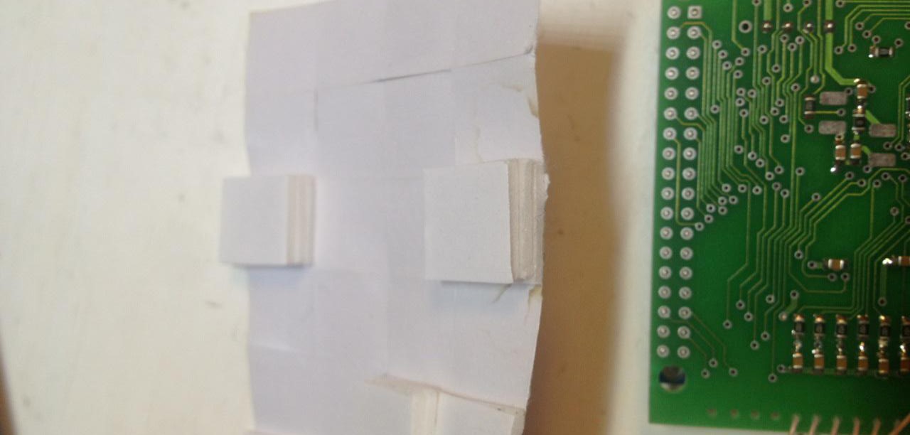
25. And we place them so that we do not have anything to do with mounting the module on the board
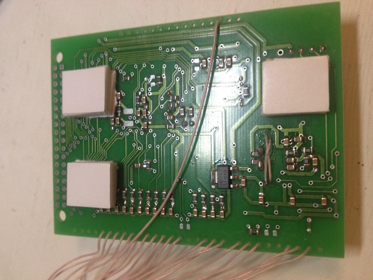
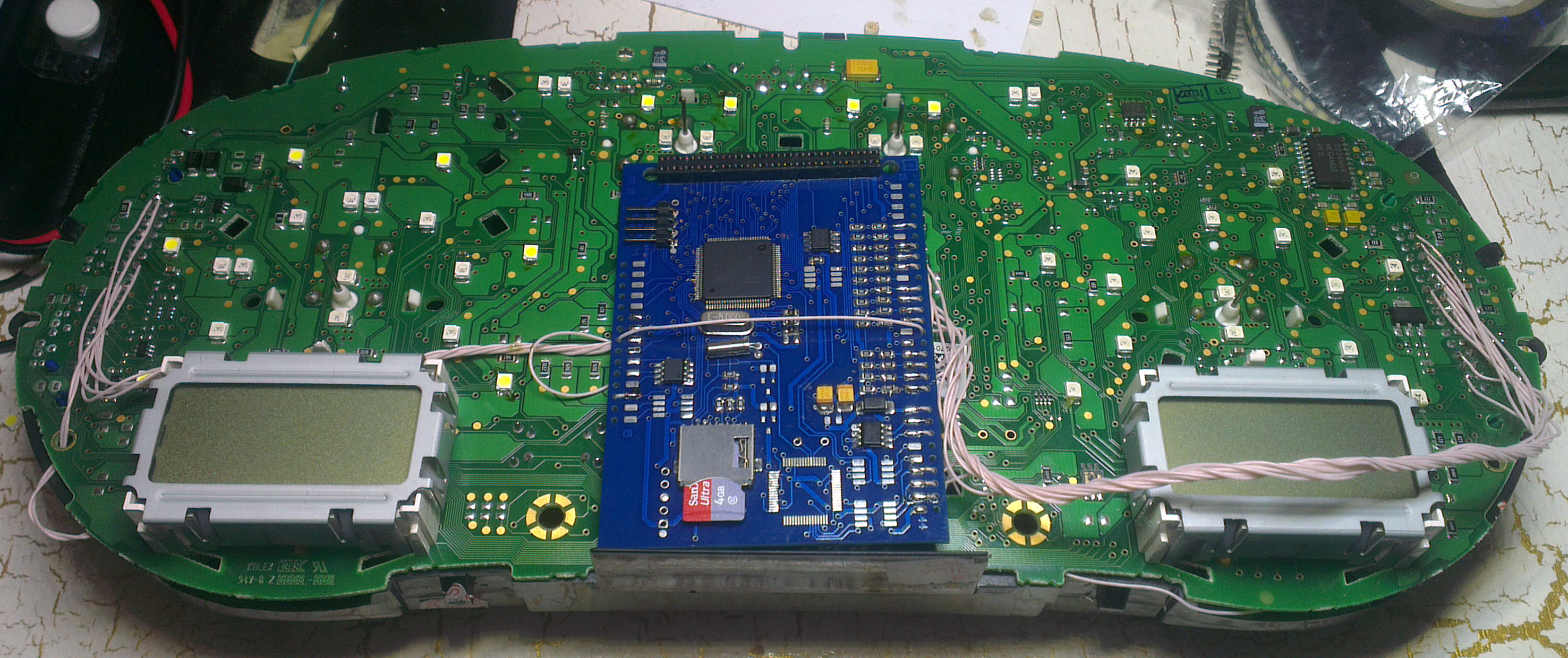
26. Place the module so that it is placed in the window of the device

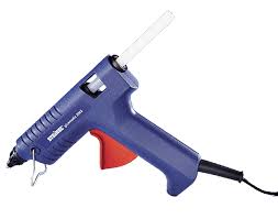
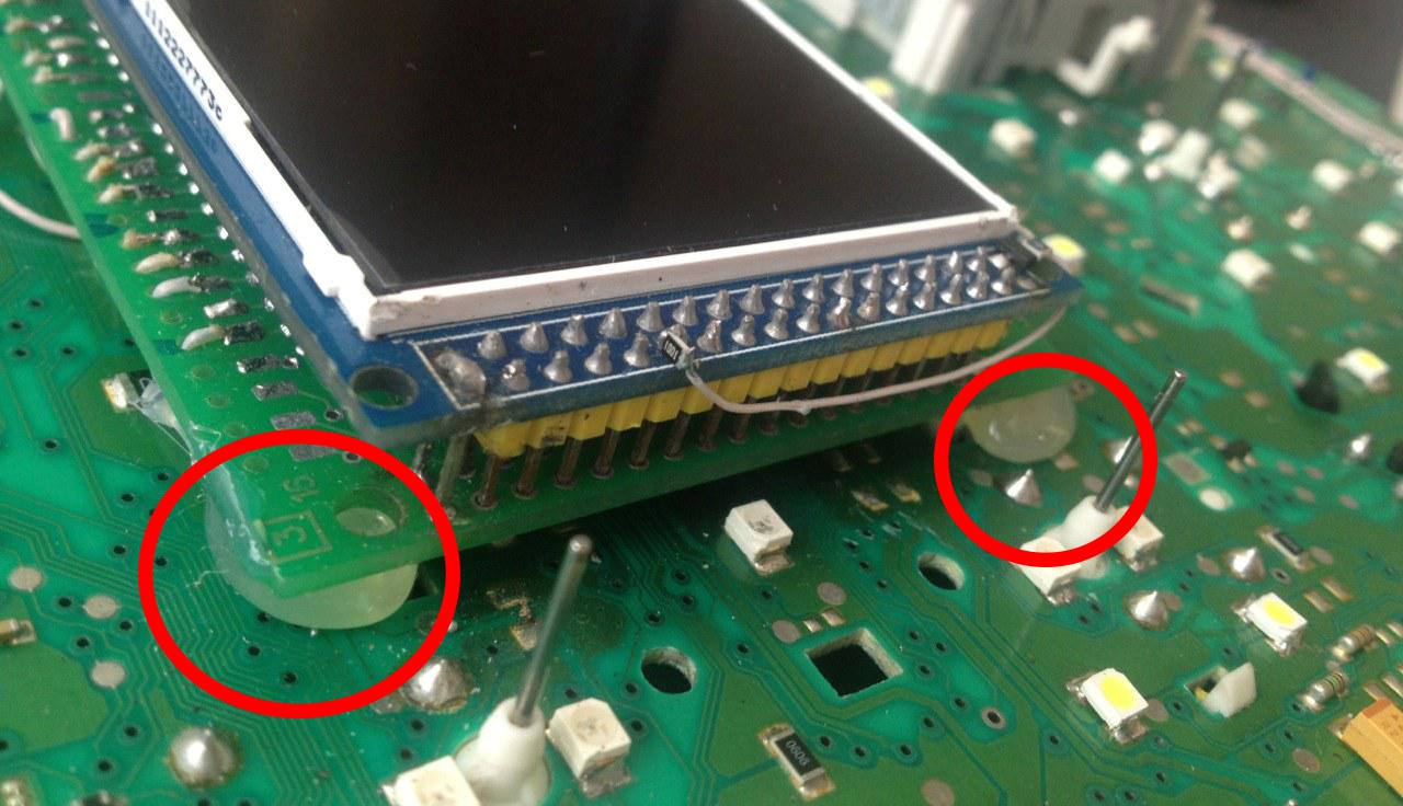
27. For greater reliability, when the module is already installed on the board, and you calibrated it in the window so that there were no distortions, it is better to fix it.
Its hot glue along the edges of the module.
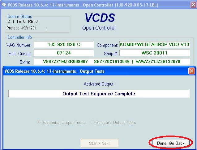
And then we collect everything in the reverse order without forgetting to calibrate the needles with the help of the WAG-com.
I. To do this, connect the device to the machine without installing the glass, connect the VAG-com,
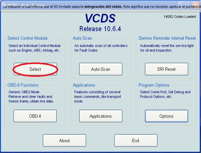
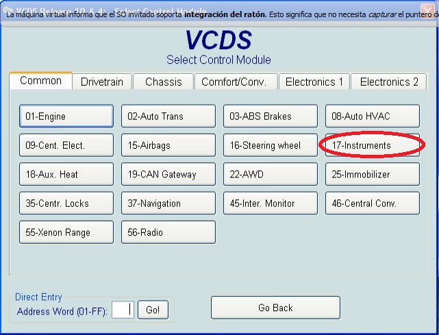
Ii. Go into the 17-unit dash panel
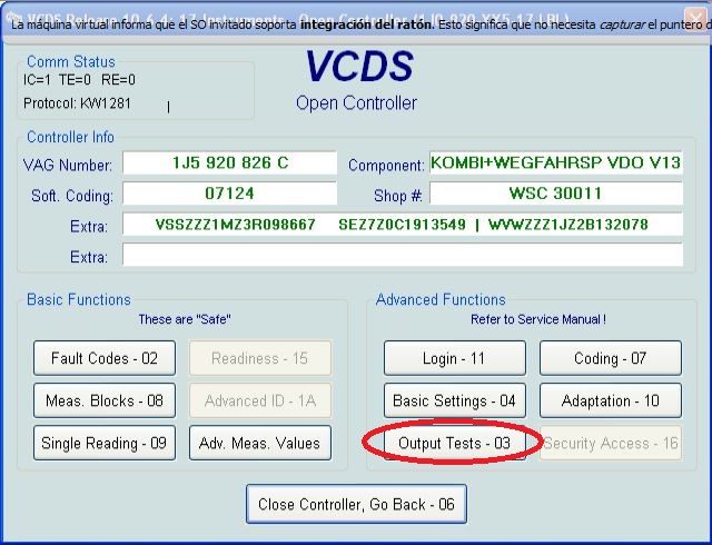
Iii. Select test performers.
Iv. Choosing in turn a tachometer, temperature and the rest, the arrows in turn will be
Do a turn on the whole scale, and then freeze on:
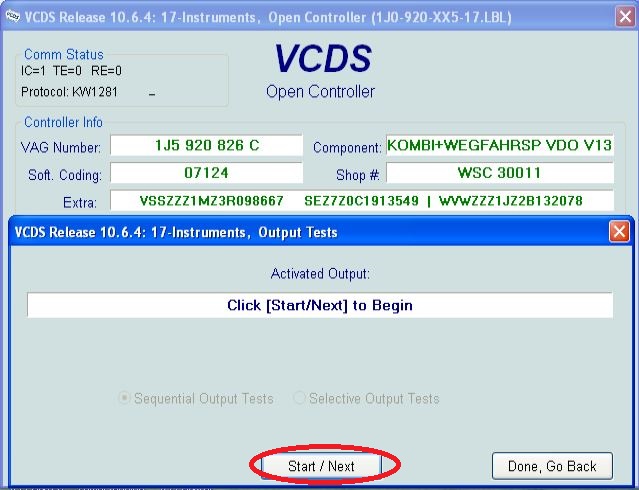
1. Tachometer - 3 thousand revolutions
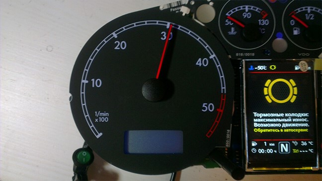
2. Pace. Coolant - middle
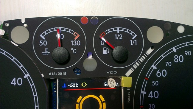
3. Fuel level - middle
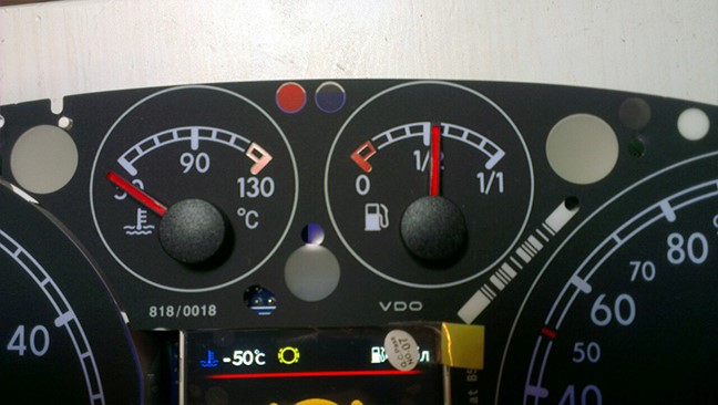
4. Speedometer - at 100 km / h
V. Then turn off the power from the device!
Vi. And set the arrows correctly rotating them in the desired direction.
Vii. Then check everything again
Viii. You can not turn the needles too quickly correcting the position, you can to damage the motors of the needles
Ix. You can not turn the arrows when there is power on the device.
Make a hole in the bottom of the cluster body, opposite the SD card, so that it can be removed if necessary.
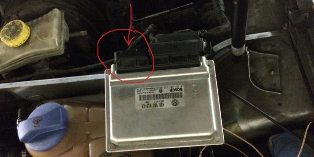
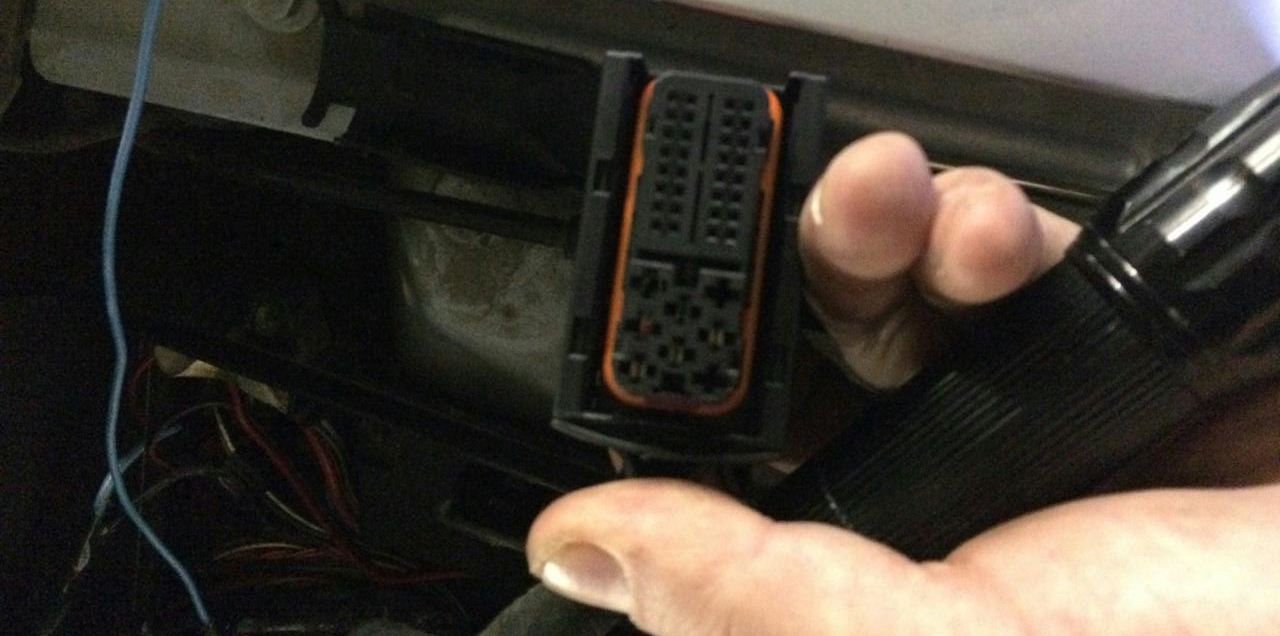
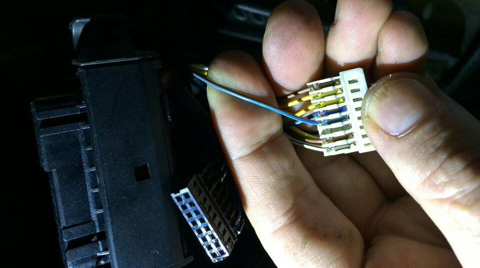
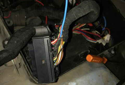
And the other end of the wire should be connected from the side of the motor brain
(EBCUD to a blue - gray wire (blue with a gray bar) to the incoming
On the 101st contact of a smaller brain connector.
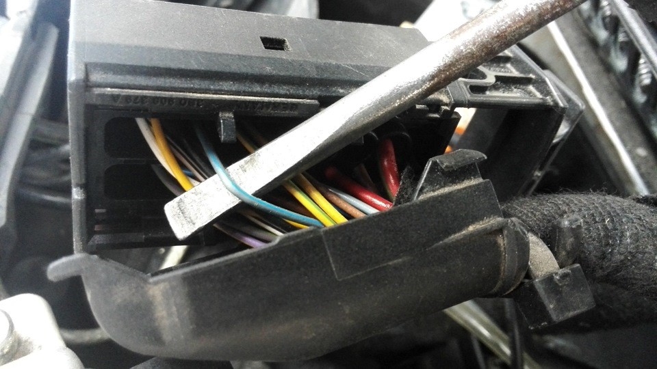
On
diesel engines (AVB and others):
- 71st
contact of the motor
brain, green - red Wire
(green with a red stripe).
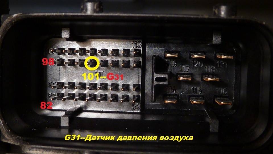
On
petrol (AWM and others):
- 101st
contact of the motor
brain, gray - blue wire
(gray with a blue stripe).
In general, as far as I understand, at all B5-x diesel 1.9T supercharging is connected to the 71st
And the gasoline 1.8T is connected to the 101st contact. The color of the wire can vary depending on the year / engine.
| BES | 2.7T | T121 | 101 pin | blue-gray | AJM | 1.9TD | T121 | 71 pin | yellow-black | |
| AKN | 2.5TD | T121 | 71 pin | yellow-red | AUY | 1.9TD | T121 | 71 pin | yellow-black | |
| BQW | 2.0TD | T94 | 78 pin | green-red | AWT | 1.8T | T121 | 101 pin | blue-gray | |
| AVG | 1.9TD | T80 | 40 pin | yellow-green | AWM | 1.8T | T121 | 101 pin | blue-gray | |
| AFN | 1.9TD | T121 | 70 pin | green-red | AWD | 1.8T | T121 | 101 pin | blue-gray | |
| AVB | 1.9TD | T121 | 71 pin | green-red | AWP | 1.8T | T121 | 101 pin | violet-gray | |
| AVF | 1.9TD | T121 | 71 pin | green-red | AUM | 1.8T | T121 | 101 pin | violet-gray | |
| AWX | 1.9TD | T121 | 71 pin | green-red | AUQ | 1.8T | T121 | 101 pin | violet-gray | |
| AHF | 1.9TD | T121 | 71 pin | yellow-black | ARZ | 1.8T | T121 | 101 pin | violet-gray | |
| ALH | 1.9TD | T121 | 71 pin | yellow-black | ARX | 1.8T | T121 | 101 pin | violet-gray | |
| ARL | 1.9TD | T121 | 71 pin | yellow-black | ANB | 1.8T | T121 | 101 pin | blue-gray | |
| ASV | 1.9TD | T121 | 71 pin | yellow-black | APU | 1.8T | T121 | 101 pin | blue-gray | |
| ASZ | 1.9TD | T121 | 71 pin | yellow-black | APB | 1.8T | T121 | 101 pin | blue-gray | |
| ATD | 1.9TD | T121 | 71 pin | yellow-black | AMB | 1.8T | T121 | 101 pin | blue-gray | |
| AXR | 1.9TD | T121 | 71 pin | yellow-black |
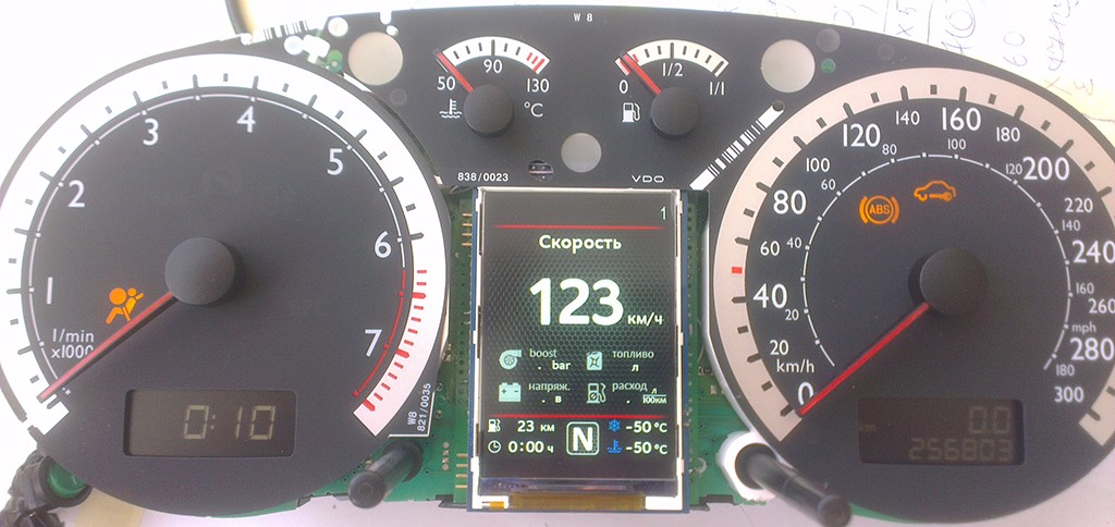
And everything is ready.
Do not assemble the instrument panel (retro-reflector, scales,
arrows and glass) to
As long as you do not test the work of the module in the Car.
It is advisable not to collect plastic steering column for a week,
In the case of the need to remove the instrument panel without unnecessary difficulties.
To make sure the device is working, and most importantly
Uninterrupted operation of the micro SD card installed in it.